This chapter describes the installation procedure for the compact router outdoor type (AC25) with wireless LAN.
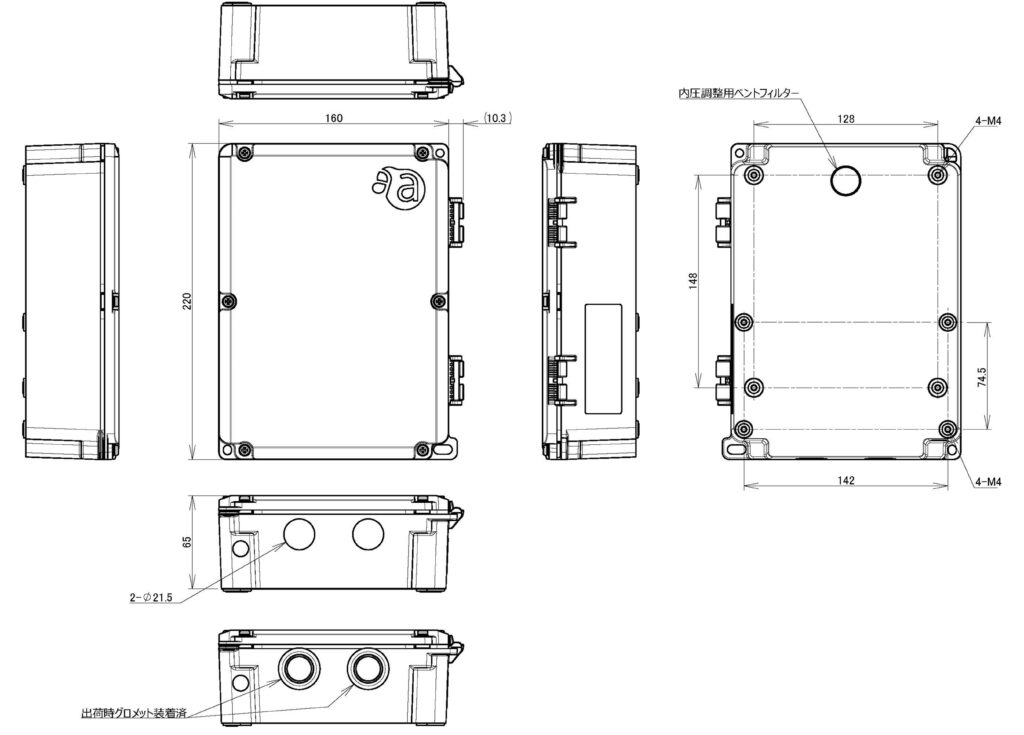
Outline Drawing #
- Weight: approx. 1.1 kg
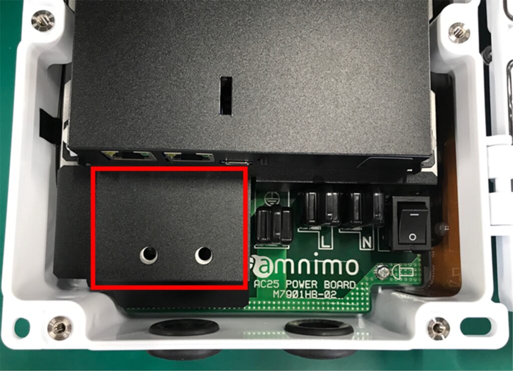
About power supply connection #
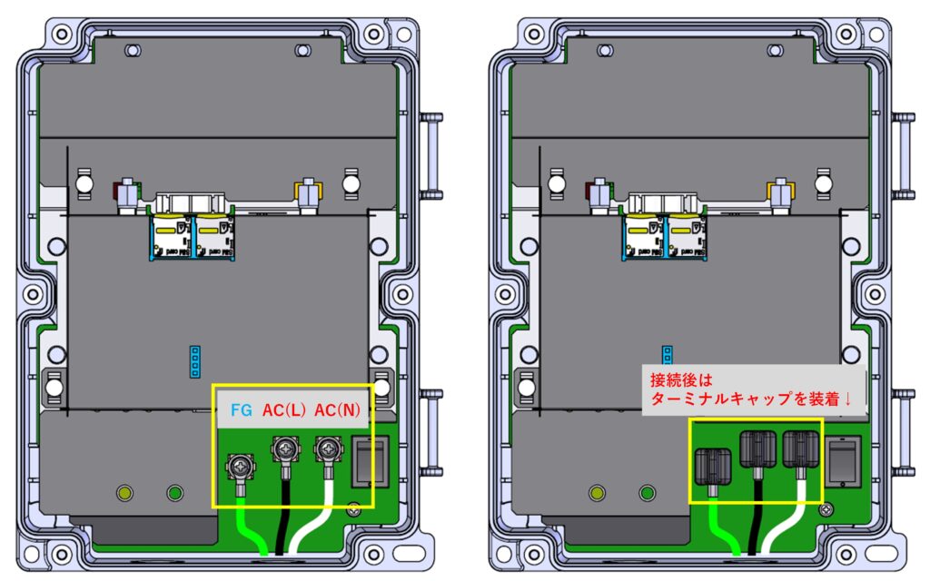
- For power supply connection, connect 100 VAC (L side and N side) and FG (frame ground) as shown above.
- The FG mark and the L side are clearly marked near the connector.
- FG must be connected, otherwise accidents or malfunctions may occur.
- Please be very careful not to touch these terminals with metal or your body by mistake.
- After connecting the power supply, work in such a way that the power supply to the equipment can be cut off by installing an NFB (wiring circuit breaker) on the AC100V power line.
- After connecting the power supply, attach terminal caps to the terminal block.
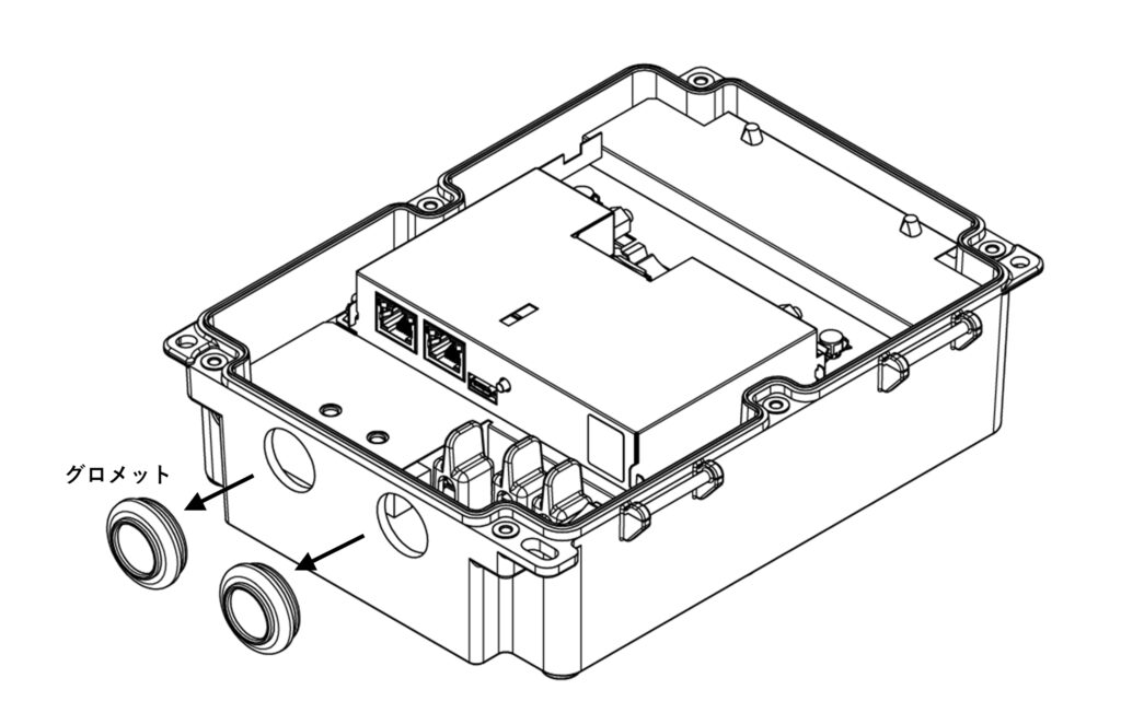
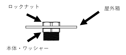
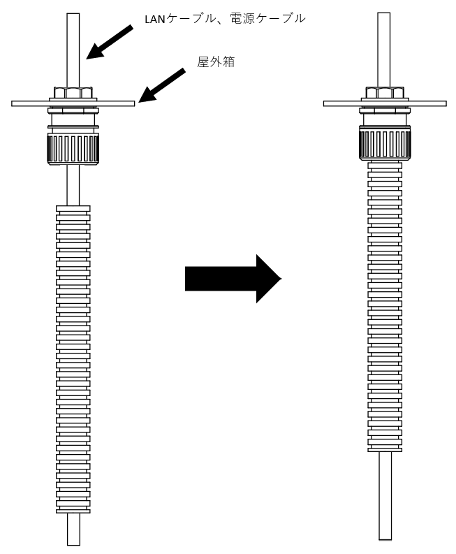
When using a cable gland #
necessities #
| Cable gland (recommended) * sold separately |
|---|
| M7901YR (FGB21L-14B) * For power cable https://www.ip68.jp/products/210_2010_b_products.html |
| M7901YQ (FGA21L-10B-SD) * For Ether cable https://www.ip68.jp/products/210_2015_products.html |
| M7901YY (FGA21L-06B-SD) * For Ethernet cable https://www.ip68.jp/products/210_2015_products.html |
| M7901YZ (FGA21L-H2-06B-SD) * For Ether cable (when 2 cables are used) https://www.ip68.jp/products/210_8010_products.html |
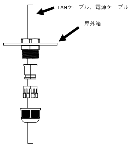
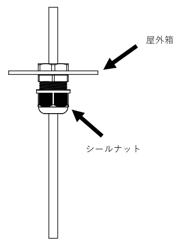
Installation Instructions #
- To run two Ether cables through one cable gland, use a cable gland for two ports.
- It is not possible to pull out all wiring using only the standard holes. Additional hole fabrication may be required, so please contact your Amnimo sales representative before purchasing.
- Use LAN cables with compatible wire diameters.
⇒Refer to Accessories (sold separately). - When using a cable with RJ-45, use a connector diameter of 14 mm or smaller.
- When using connectors larger than 14 mm, crimp the connectors after passing through the cable gland.
When using PF pipe connectors #
necessities #
| PF pipe connector with verified connection * Not sold by Amnimo |
|---|
| Furukawa Electric: PFS-16KSR-I (IPX5 compliant product) https://www.furukawa.co.jp/eflex/product/plafleky/p_pfbkr.htm |
| Mirai Kogyo: FPK16YPS (IPX7 compliant product) https://www.mirai.co.jp/densetu/pdf-catalog_2021/6000221.pdf |
Installation Instructions #
There is no manufacturer's recommended tightening torque for both PF pipe connectors.
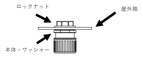
It is not possible to pull out all the wires using only the standard holes. Additional hole machining may be required, so please consult your Amnimo sales representative prior to purchase.
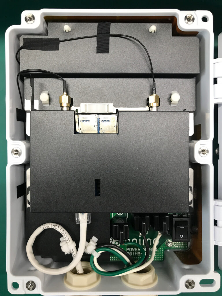
Internal wiring and wiring treatment #
necessities #
Cable ties for fixing cables (2 pcs. included) *If you need more, please procure and use the following model number.
- (Recommended) Takeuchi Kogyo Reuse Snapping Ties RST-130V0
Wire connection example #
Since cables are not fixed when using PF Suga, the following procedure can be used to fix cables to prevent stress on connectors and terminal blocks.
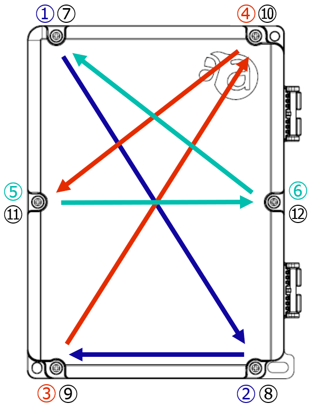
Order of cover screw tightening #
During installation, torque the door evenly and tighten the screws in the order shown in the figure to prevent water intrusion.
Tighten the screws temporarily in the order of (1) through (6), and then tighten them again in the order of (7) through (12).
Tightening torque: 1.2 N-m
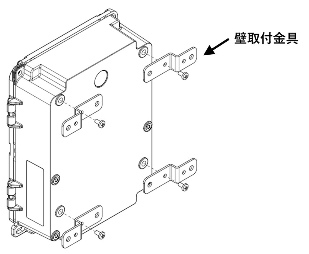
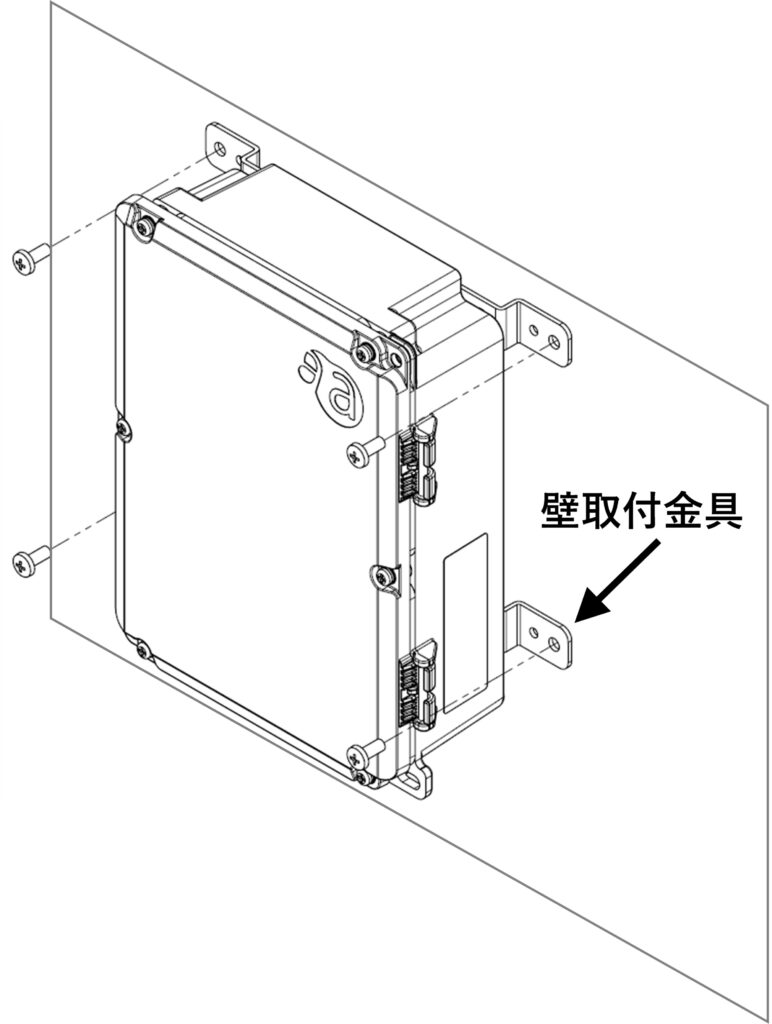
About wall installation #
necessities #
| Wall mounting bracket (recommended) * Sold separately |
|---|
| M7901ZE |
Mounting example #
When installing on a wall, use appropriate bolts or screws that can withstand the weight of the unit against a sufficiently strong wall surface. When attaching the metal fittings to the box, use a tightening torque of 1.0 N-m as a guide for installation.
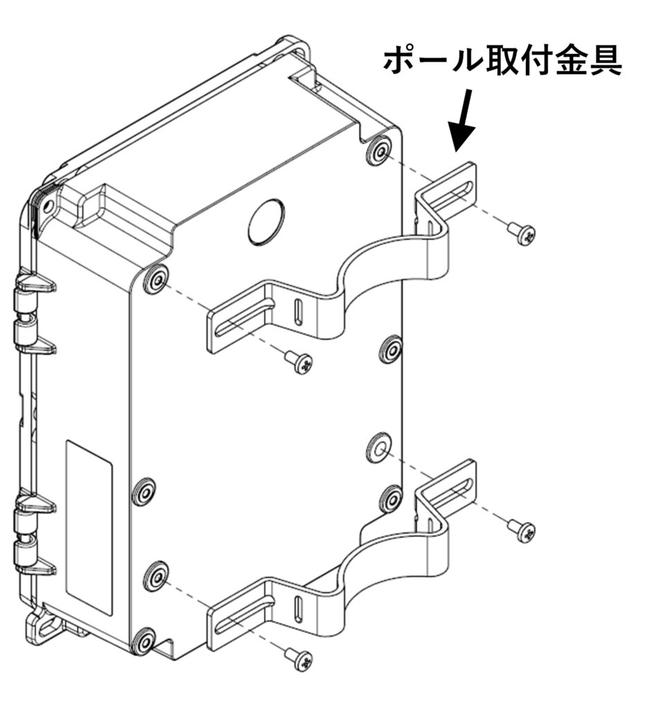
Pole Installation #
necessities #
| Pole mounting bracket (recommended) * Compatible pole/con pillar diameter 60 to 400 mm M7901ZD |
| Pole mounting band (recommended) * Compatible pole/con pillar diameter 60 to 400 mm M7901YU (PKB-10S) https://www.takachi-el.co.jp/products/PKB |
Mounting example #
When attaching metal fittings to the box, use a tightening torque of 1.0 N-m as a guide for installation.
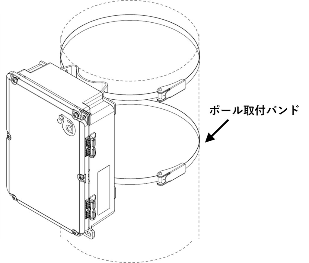
Please refer to the following page from the manufacturer for belt installation instructions.
https://www.takachi-el.co.jp/assets/attachments/images/PKB10S_PKB20S_manual.pdf
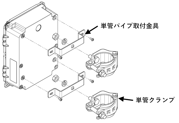
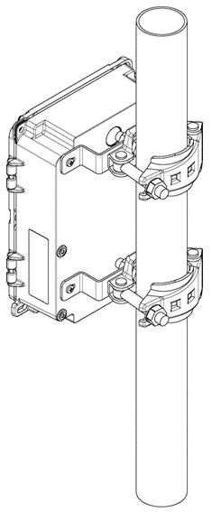
Single Pipe Installation #
necessities #
| Single pipe mounting bracket set (recommended) * Applicable single pipe diameter 42.7-48.6mm |
|---|
| M7901ZF |
Mounting example #
When attaching metal fittings to the box, use a tightening torque of 1.0 N-m as a guide for installation.
About Camera Mounting Bracket Sets #
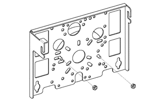
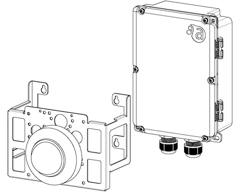
Camera Mounting Bracket Set (Separate Type) #
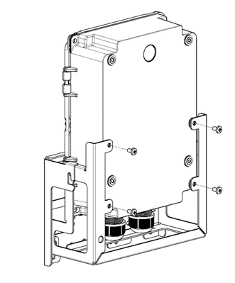
The camera plate section can be removed by slightly loosening the screws.
Note that if you loosen the screws all the way to the end with an electric screwdriver, etc., the washers that prevent the screws from falling out will come off.
Refer to the following for the mounting position of each camera.
⇒[ AC25] Camera mounting bracket: List of mounting holes for each camera
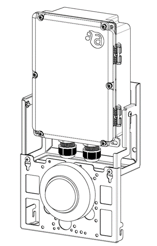
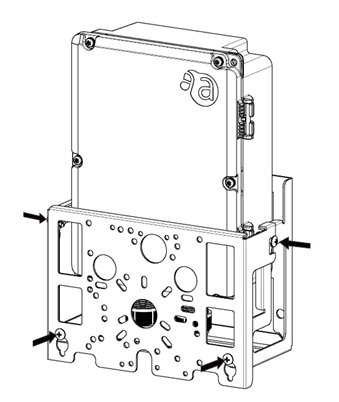
Camera mounting bracket set (integrated type) #
Refer to the following for the mounting position of each camera.
⇒[ AC25] Camera mounting bracket: List of mounting holes for each camera
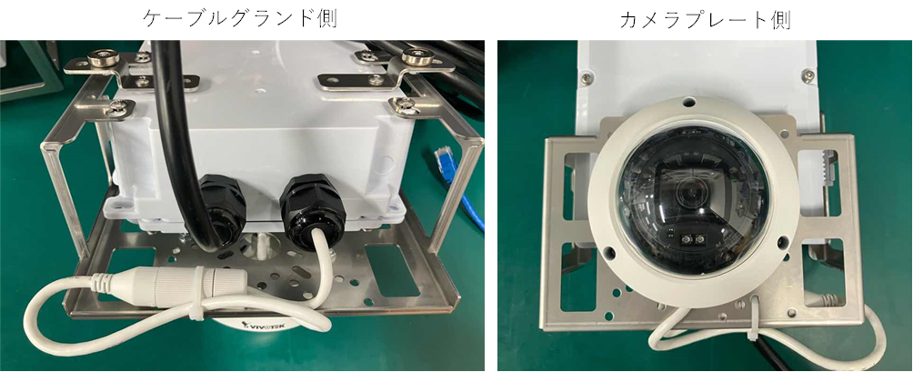
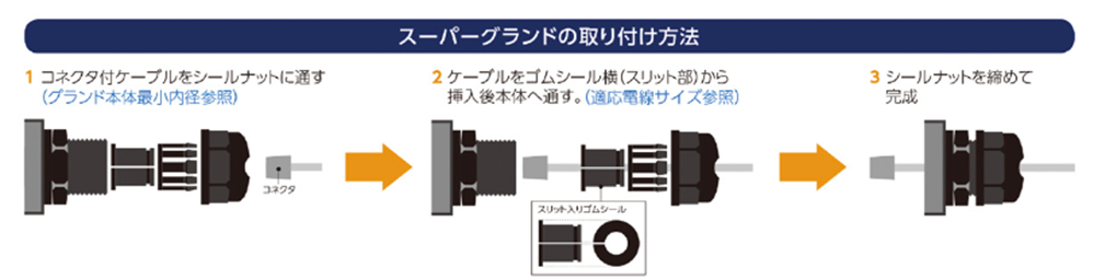
Cable installation method for camera mounting bracket set #
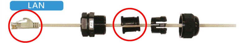
Cable ground section
In Amnimo's standard optional cable gland, there is a slit in the rubber shield section, so the jack part of the LAN cable can be passed through.
The slit makes it a cable gland that allows even small, pre-installed connectors to pass through.
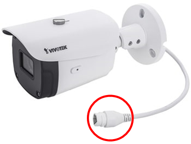
Camera-side connector
The connector on the camera side is too large to pass through the cable gland.
Use the waterproof connector supplied with the camera.
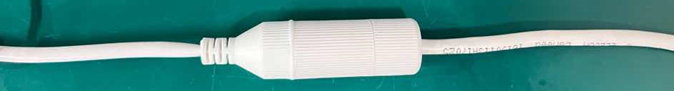
Waterproof cap on camera side
When using Amnimo's standard optional cable gland for normal installation, make connections outside of the cable gland.
Use the waterproof cap provided with the camera.
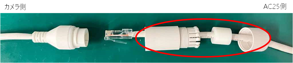
Waterproofing is secured here. Add waterproofing tape if necessary.
Cable Fixing
For excess cable length treatment, use the holes in the camera fittings and secure with cable ties.