
This section describes the basic configuration of the IoT router itself.
IoT Router (indoor version) #
This section describes the basic configuration of the IoT Router (indoor version) main unit.
facade
The configuration of the front panel (with the lid of the SD card section open) is shown below.
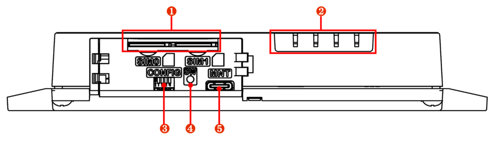
| No. | name | Description. |
| ❶ | SIM card slot 0, SIM card slot 1 | Two SIM cards can be inserted in the SIM card slot. The priority level changes depending on the setting. By default, SIM 0 is used. The AR10-000JP model does not have a SIM card slot. |
| ❷ | LED Indicator | From left to right, they are arranged as PWR, ANT, MOB, and ST. The description of each LED is as follows PWR: Shows the power status. ANT: Displays the antenna status. MOB: Shows the line connection status of the communication module. ST: Shows specific status in combination with other indicators. For AR10-000JP models, the notation will change: ANT will be OPT2, MOB will be OPT1, and the status will be uncontrolled. |
| ❸ | DIP switches for configuration | Sets the startup mode of the IoT router. |
| ❹ | PUSH switch | Used to shut down the IoT router or restore it to factory settings. |
| (in Japanese) ❺ | CONSOLE Port | Used to configure the IoT router; connects via USB Type-C connector. |
back
The rear configuration is shown below.
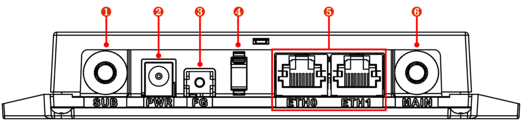
| No. | name | Description. |
| ❶ | subantenna | Connect antenna for 3G/4G line, SMA-J type. |
| ❷ | PWR | Connect AC adapter (sold separately) or DC power cable. Center positive, Φ2.1 DC jack connector. |
| ❸ | FG | Connect frame ground. Connect M3 crimp terminals. |
| ❹ | cable clamp | Prevents power cable disconnection. |
| (in Japanese) ❺ | ETH0 and ETH1 ports | Standard Ethernet port with Gigabit Ethernet support. |
| (in Japanese) ❻ | main antenna | Connect antenna for 3G/4G line, SMA-J type. |
When connecting a DC power cable to the PWR, use it within the rated voltage.
The AR10-000JP model does not have main or sub-antenna terminals.
three-sided view
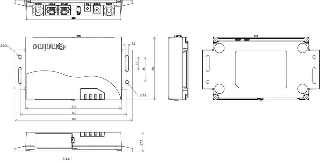
Three views of the IoT router are shown below.
IoT Router (outdoor version) #
This section describes the basic configuration of the IoT Router (outdoor version) itself.
Front (lid open)
The configuration of the front view when the lid is open is shown below.
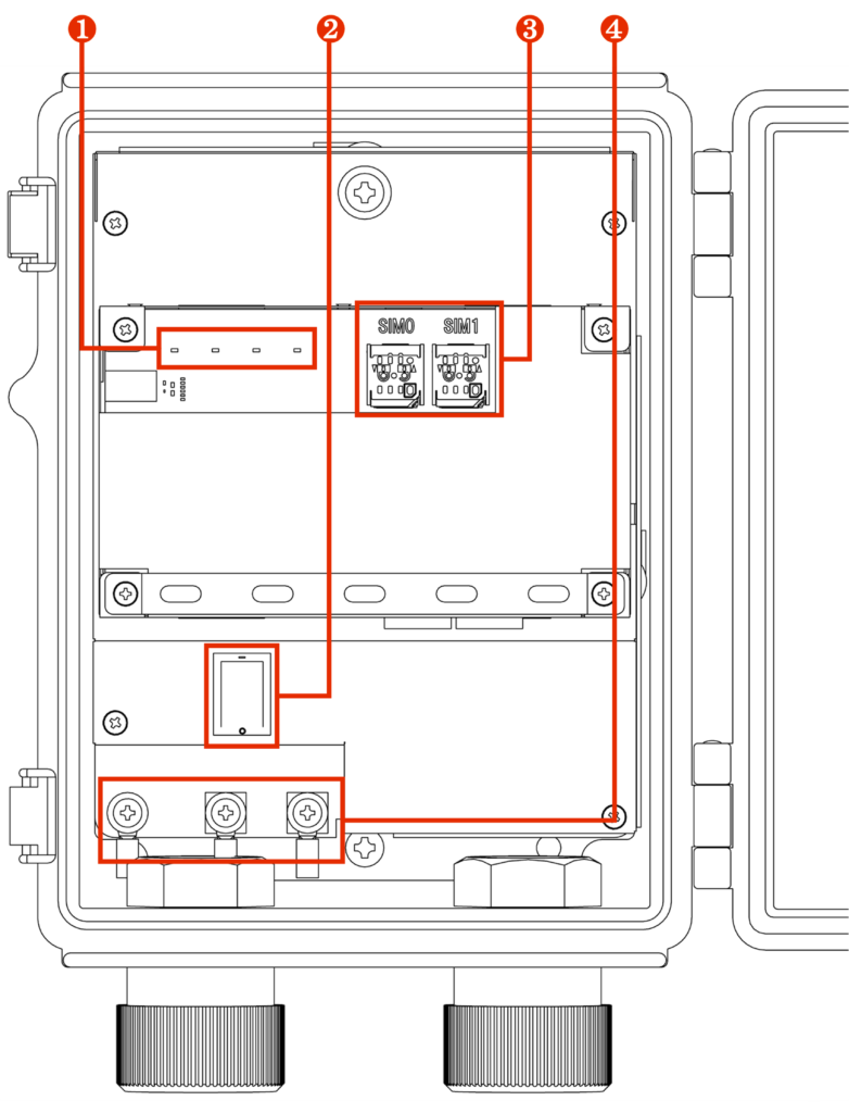
| No. | name | Description. |
| ❶ | LED Indicator | From left to right, they are arranged as PWR, ANT, MOB, and ST. The description of each LED is as follows PWR: Displays the power supply status. ANT: Displays the antenna status. MOB: Shows the line connection status of the communication module. ST: In combination with other indicators, a specific state is indicated. |
| ❷ | power switch | Turns power on and off. |
| ❸ | SIM card slot 0, SIM card slot 1 | Two SIM cards can be inserted in the SIM card slot. The priority level changes depending on the setting. By default, SIM 0 is used. |
| ❹ | AC power input terminal | From left to right: FG, L (ungrounded side), N (grounded side). Screw shape is M4. |
Diagonal front 1 (lid open)
The diagonal frontal configuration is shown below.
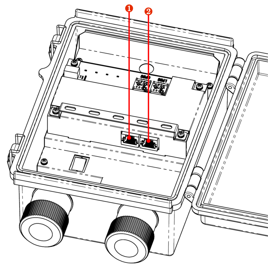
| No. | name | Description. |
| ❶ | ETH0 port | Standard Ethernet port with Gigabit Ethernet support. |
| ❷ | ETH1 port | Standard Ethernet port with Gigabit Ethernet support. |
Diagonal front 2 (lid open)
The diagonal frontal configuration is shown below.
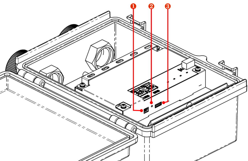
| No. | name | Description. |
| ❶ | DIP switches for configuration | Sets the startup mode of the IoT router. |
| ❷ | PUSH switch | Used to shut down the IoT router or restore it to factory settings. |
| ❸ | CONSOLE Port | Used to configure the IoT router; connects via USB Type-C connector. |
three-sided view
A three-view diagram is shown below.
