This section describes the basic configuration of the compact router itself.
Indoor Compact Router #
This section describes the basic configuration of the main unit of the indoor type compact router.
facade #
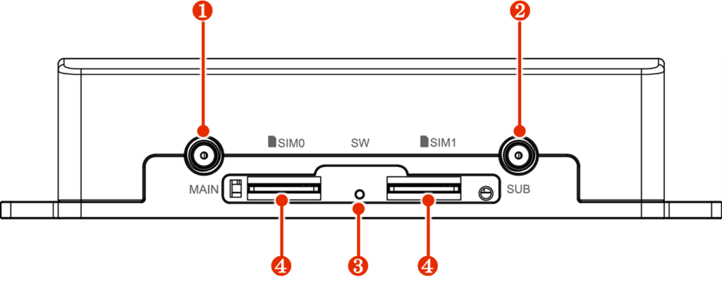
The configuration on the front of the compact router is shown below.
The lid of the compact router can be opened. The figure below shows the lid in the open position.
| No. | Display name | name | Description. |
| ❶ | MAIN | Main antenna*. | Connect antenna for 3G/4G line, SMA-J type. |
| ❷ | sub | Sub Antenna*. | Connect antenna for 3G/4G line, SMA-J type. |
| ❸ | SW | PUSH switch | Used to restore the compact router to factory settings or to shut it down. |
| ❹ | SIM0 SIM1 | SIM card slot 0 SIM card slot 1 | There are two inserts as SIM card slots, and two SIM cards can be inserted. The priority of the SIM card depends on the settings. By default, the SIM card inserted in SIM 0 is used. |
However, if the signal environment at the installation site is poor, the reception sensitivity can be improved by connecting an antenna (sold separately).
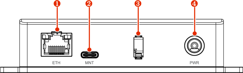
back #
The rear of the compact router is shown below.
| No. | Display name | name | Description. |
| ❶ | ethylenediaminetetraacetic acid | Ethernet port | Standard 100BASE-TX Ethernet port. |
| ❷ | MNT | console port | Used to configure the compact router; connects via USB Type-C connector. |
| ❸ | ― | cable clamp | Prevents power cable disconnection. |
| ❹ | PWR | PWR | Connect optional AC adapter or DC power cable. Center positive, Φ2.1 DC jack connector. |
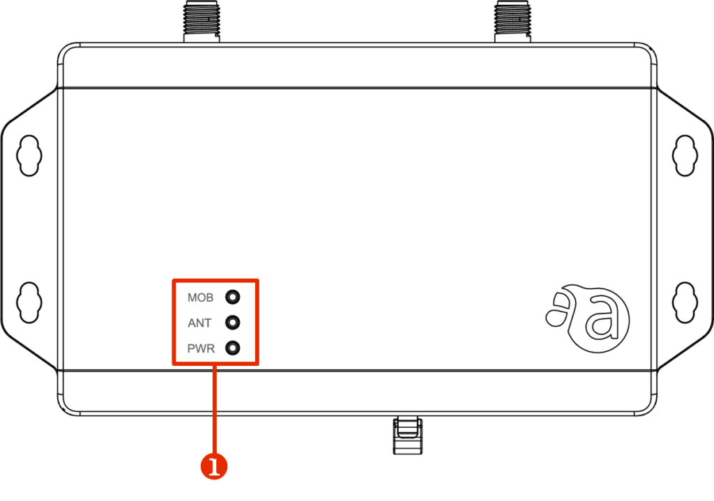
surface #
The top face of the compact router is configured as follows.
| No. | Display name | name | Description. |
| ❶ | MOB ANT PWR | LED Indicator | The meaning of each LED is as follows MOB: Shows the line connection status of the communication module. ANT: Displays the antenna status. PWR: Displays the power supply status. |
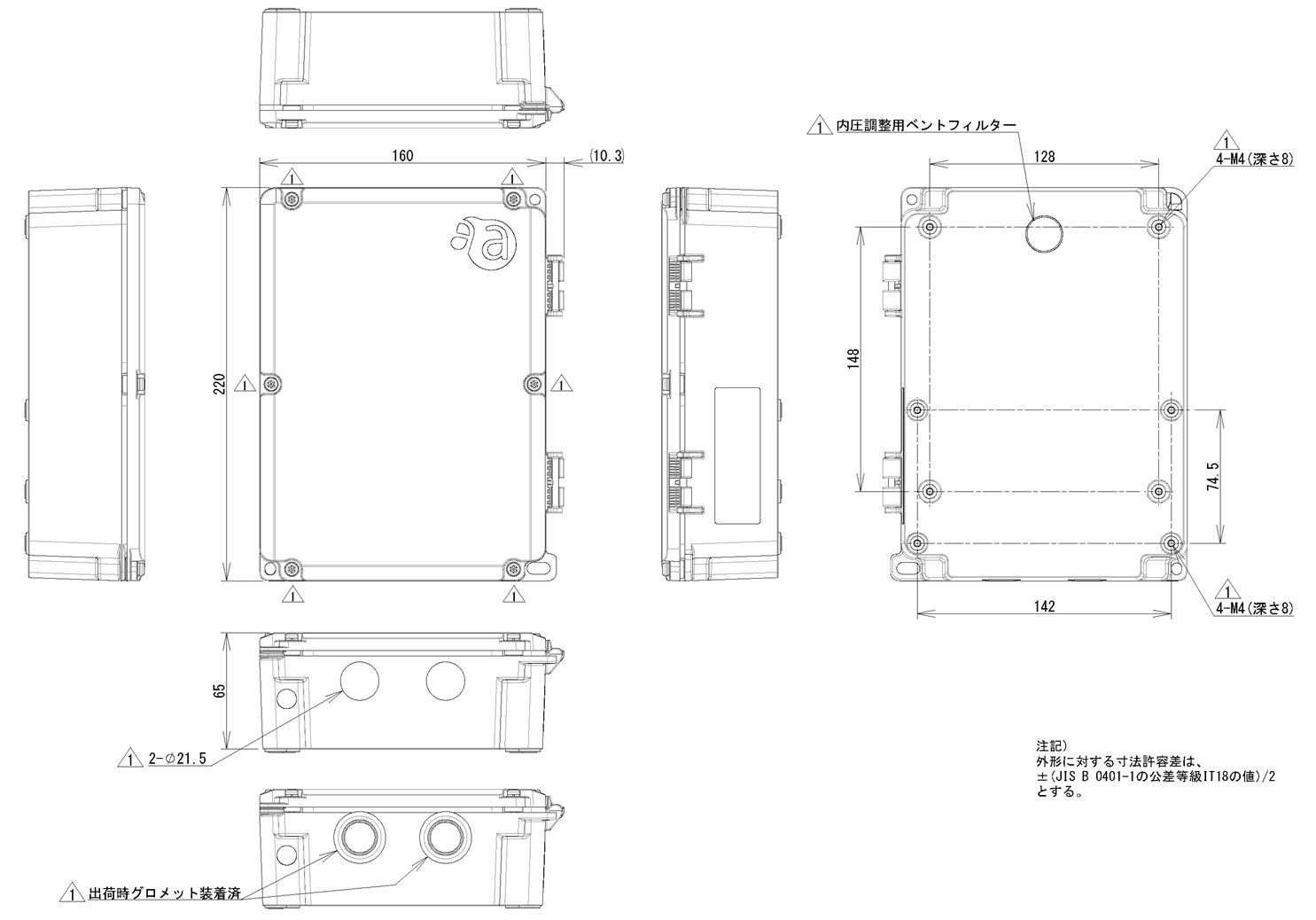
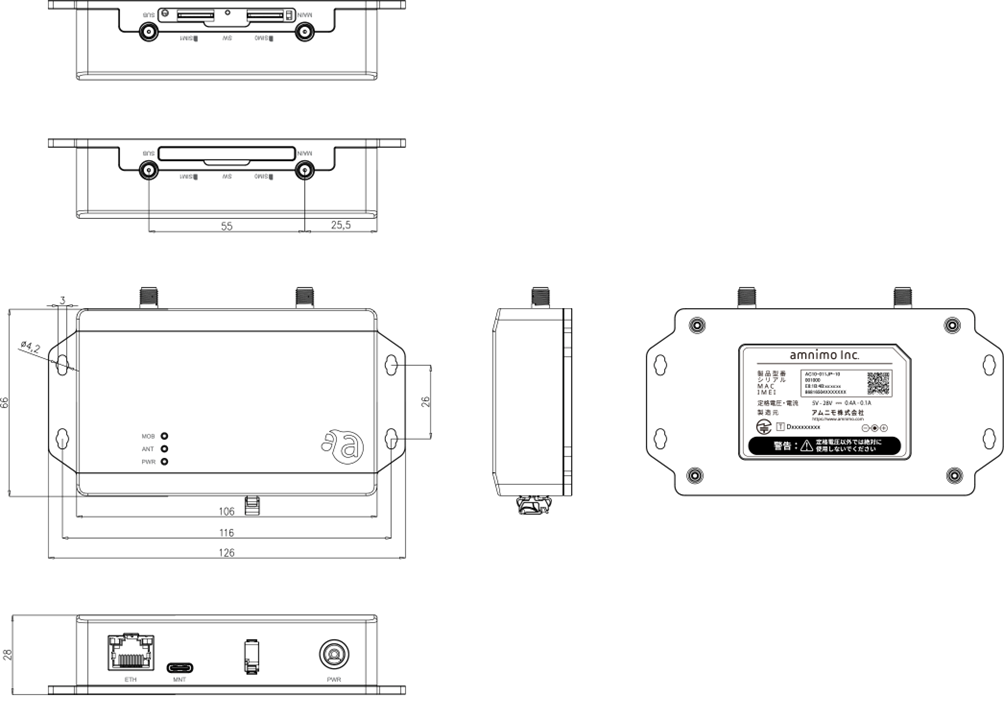
three-sided view #
Three views of the compact router are shown below.
Compact router with indoor type wireless LAN #
This section describes the basic configuration of the main unit of the compact router with indoor type wireless LAN.
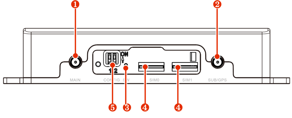
facade #
The front of the compact router with indoor type wireless LAN is shown below.
The lid of the compact router with indoor wireless LAN can be opened. The figure below shows the lid in the open position.
| No. | Display name | name | Description. |
| ❶ | MAIN | Main antenna*1 | Connect antenna for 3G/4G line, SMA-J type. |
| ❷ | SUB/GPS | Sub antenna*1/GPSantenna*2 | Connect GNSS or 3G/4G line antenna. |
| ❸ | SW | PUSH switch | Used to restore the compact router to factory settings or to shut it down. |
| ❹ | SIM0 SIM1 | SIM card slot 0 SIM card slot 1 | There are two inserts as SIM card slots, and two SIM cards can be inserted. The priority of the SIM card depends on the settings. By default, the SIM card inserted in SIM 0 is used. |
| (in Japanese) ❺ | CONFIG | DIP switch | Dip switches for maintenance. (To be used in future releases) |
1 Since the compact router has a built-in 3G/4G antenna, there is basically no need to connect an antenna. However, if the signal environment in the installation location is poor, the reception sensitivity can be improved by connecting an antenna (sold separately).
2 Exclusive use with LTE. Passive antennas are supported.
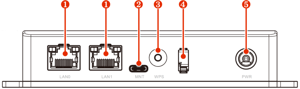
back #
The rear of the compact router with indoor type wireless LAN is shown below.
| No. | Display name | name | Description. |
| ❶ | LAN0 LAN1 | Ethernet port | Standard 100BASE-TX Ethernet port. |
| ❷ | MNT | console port | Used to configure the compact router; connects via USB Type-C connector. |
| ❸ | WPS | WPS button | Used for wireless LAN connections using the WPS function. |
| ❹ | ― | cable clamp | Prevents power cable disconnection. |
| ❹ | PWR | PWR | Connect optional AC adapter or DC power cable. Center positive, Φ2.1 DC jack connector. |
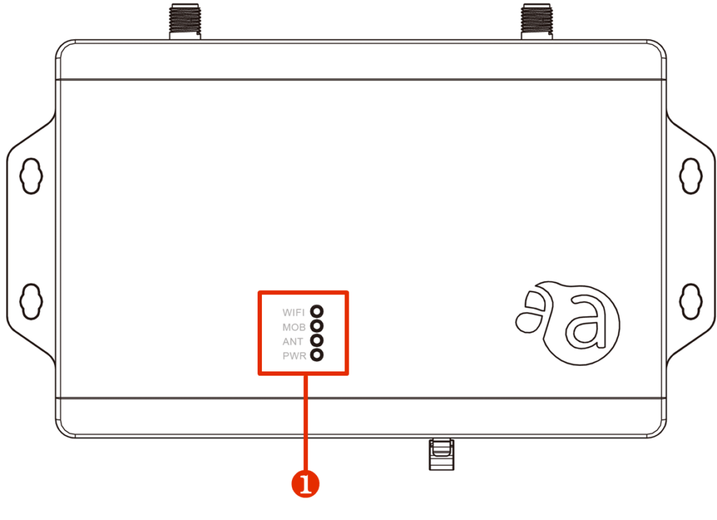
surface #
The top view of the compact router with indoor type wireless LAN is shown below.
| No. | Display name | name | Description. |
| ❶ | WIFI MOB ANT PWR | LED Indicator | The meaning of each LED is as follows WIFI: Shows the status of the wireless LAN connection. MOB: Shows the line connection status of the communication module. ANT: Shows the antenna status. PWR: Shows the power status. |
three-sided view #
Three views of the compact router with indoor type wireless LAN are shown below.
Compact router with outdoor type wireless LAN #
This section describes the basic configuration of the main unit of the compact router with outdoor type wireless LAN.
Front (lid open) #
The configuration of the front view when the lid is open is shown below.
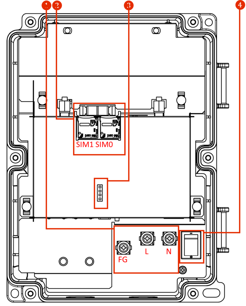
| No. | name | Description. |
| ❶ | AC power input terminal | From left to right: FG, L (ungrounded side), N (grounded side). Screw shape is M4. |
| ❷ | SIM card slot 0, SIM card slot 1 | Two microSIM cards can be inserted in the SIM card slot. The priority level changes depending on the setting. By default, SIM 0 is used. |
| ❸ | LED Indicator | The meaning of each LED is as follows WIFI: Shows the status of the wireless LAN connection. MOB: Shows the line connection status of the communication module. ANT: Shows the antenna status. PWR: Shows the power status. |
| ❹ | power switch | Turns power on and off. -: ON: OFF |
Diagonal front 1 (lid open) #
The diagonal frontal configuration is shown below.
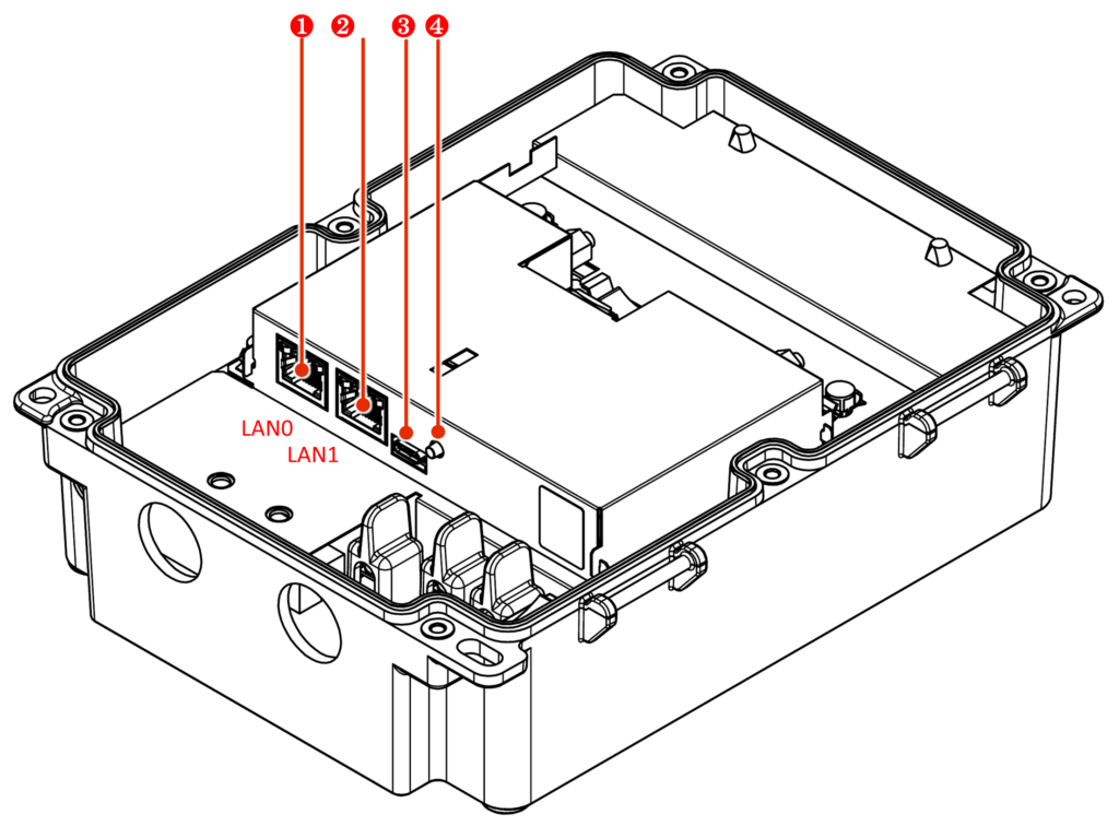
| No. | name | Description. |
| ❶ | LAN0 port | Standard 100BASE-TX Ethernet port. |
| ❷ | LAN1 port | Standard 100BASE-TX Ethernet port. The LAN1 port side is PoE-compatible. |
| ❸ | CONSOLE Port | Used to configure the compact router; connects via USB Type-C connector. |
| ❹ | WPS button | Used for wireless LAN connections using the WPS function. |
Diagonal front 2 (lid open) #
The diagonal frontal configuration is shown below.
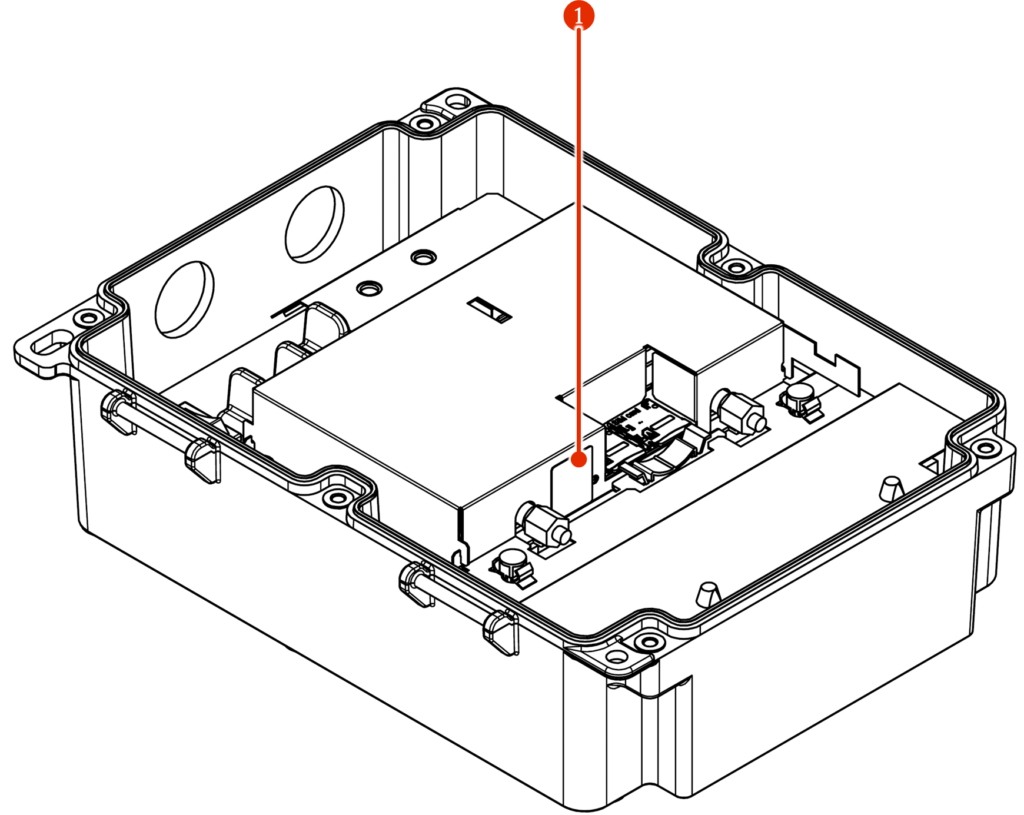
| No. | name | Description. |
| ❶ | PUSH switch | Used to restore the compact router to factory settings or to shut it down. |
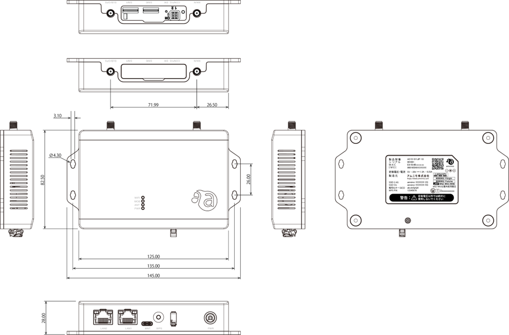
three-sided view #
A three-view diagram is shown below.