
LED
 #
#
This section describes the lighting and blinking patterns of the LEDs on the front of the IoT router.
LED Icon Description #
| LED | Description. |
 | Indicates that the red and green LEDs are off. |
 | Indicates that the red and green LEDs are lit. |
 | Indicates that the red LED is on. |
 | Indicates that the red LED is blinking. (Blinking cycle is at 500ms intervals) |
 | Indicates that the red LED is blinking. (Blinking cycle is at 125ms intervals) |
 | Indicates that the green LED is on. |
 | Indicates a blinking green LED. (Blinking cycle is at 500ms intervals) |
 | Indicates a blinking green LED. (Blinking cycle is at 125ms intervals) |
Blank columns indicate that the LEDs are not controlled. Any change of state between items has no effect.
LED Status List #
| (data) item | PWR | ANT | MOB | ST1 | ST2 | ST3 | remarks | |
| power disconnection (e.g. interrupted power supply) | | |||||||
| power-on | | | | | | | ||
| during startup (of a machine, e.g.) | | | | | | | ANT, MOB, ST1, ST2, ST3 repeatedly turn on in this order 500ms interval | |
| Startup error occurred | | |||||||
| Power outage | | 125ms interval | ||||||
| power disconnected (state) | | |||||||
| shutdown process in progress | | 500ms interval | ||||||
| Antenna Level | ||||||||
| unused | | |||||||
| usually | | RSSI (-73 dBm or higher) | ||||||
| average (e.g. quality) | | 500ms interval RSSI (-74dBm to -83dBm) | ||||||
| during (a certain time when one did or is doing something) | | 125ms interval RSSI (-84dBm to -93dBm) | ||||||
| slightly weak | | 125ms interval RSSI (-94dBm to -109dBm) | ||||||
| weak | | 500ms interval RSSI (-110dBm to -112dBm) | ||||||
| outside range | | RSSI (-113 dBm or less) | ||||||
| state of connectivity | ||||||||
| unconnected | | |||||||
| connection failure | | |||||||
| 2G connection | | 125ms interval | ||||||
| 3G Connection | | 500ms interval | ||||||
| 4G connection | | |||||||
| Firmware update in progress | | | | | | | ANT, MOB, ST1, ST2, ST3 blinking simultaneously 125ms interval | |
| Firmware update completed | | | | | | | ||
| Firmware update failure | | | | | | | ||
For AR10-000JP models, the notation changes: ANT becomes OPT2, MOB becomes OPT1, and is uncontrolled.
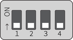
DIP switch #
The configuration DIP switch on the front of the IoT router is used to set the startup mode of the IoT router.
Explanation of DIP switch icons #
| DIP switch | Description. |
 | ON state |
 | OFF state |
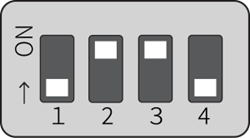
The No. 4 DIP switch can be ON or OFF. It is not referenced by the boot loader (used only on the application side).
Linux boot mode DIP switch settings
DIP switch settings for U-Boot command mode
PUSH switch #
Holding down the PUSH switch for 3 seconds after booting the OS will put the IoT router into a power-off state.
If the power-off state continues for a certain period of time, the Watchdog Timer will restart the IoT router. This makes it possible to recover from a command operation (e.g., poweroff command) without having to go to the site, even if the command operation (e.g., poweroff command) was remotely powered off by mistake.
When the DIP switch is set to "U-Boot command mode," various settings are initialized to the factory defaults by turning on the edge gateway with the PUSH switch pressed and holding the PUSH switch pressed for at least 3 seconds.
Note that setting files stored in the device will not be initialized. Therefore, if the device is rebooted after this operation is performed without writing to the settings file, it will start up with the settings before the settings are initialized.
CONSOLE Port #
The Console is USB Type-C, so a USB Type-C cable can be used.
Depending on the destination PC, the FT230X Basic UART driver may need to be installed. Please visit the following site to select the driver for your environment and follow the instructions to install it. https://ftdichip.com/drivers/d2xx-drivers/
CONSOLE port communication settings
| (data) item | Contents |
| speed | 115200 bps |
| data | 8bit |
| parity | None |
| stop bit | 1 bit |
| flow control | None |