This section describes the basic configuration of the AI Edge Gateway main unit.
AI Edge Gateway (indoor version) #
This section describes the basic configuration of the AI Edge Gateway (indoor version) main unit.
facade
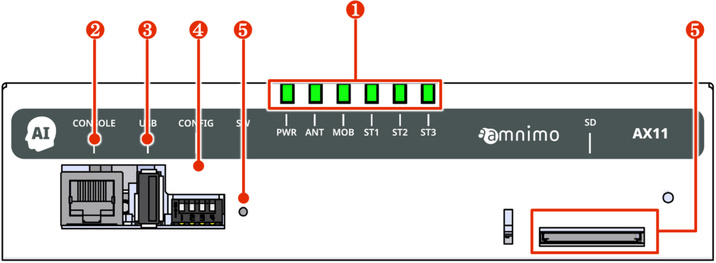
The configuration of the front panel (with the lid of the SD card section open) is shown below.
| No. | name | Description. |
| ❶ | LED Indicator | PWR: Displays the power supply status. ANT: Displays the antenna status. MOB: Shows the line connection status of the communication module. ST1, ST2, and ST3: Specific states are displayed in combination with other indicators. |
| ❷ | CONSOLE Port | Used to configure the AI Edge Gateway. |
| ❸ | USB port | Operates as a USB 2.0 host. |
| ❹ | DIP switches for configuration | Sets the startup mode of the AI Edge Gateway. |
| (in Japanese) ❺ | PUSH switch | Used to shut down the AI Edge Gateway or restore it to factory settings. |
| (in Japanese) ❻ | SD card slot | SDXC type, UHS-I compatible. |
back
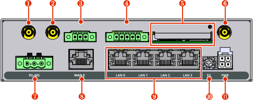
The rear configuration (with the SIM card section lid open) is shown below.
| No. | name | Description. |
| ❶ | subantenna | Connect antenna for 3G/4G line, SMA-J type. |
| ❷ | GPS antenna terminal | Connect GNSS antenna, SMA-J type. |
| ❸ | D OUT | Isolated type digital output terminal for connection to external devices. |
| ❹ | D IN | Isolated type digital input terminal for connection to external devices. |
| (in Japanese) ❺ | SIM card slot 0, SIM card slot 1 | Two SIM cards can be inserted in the SIM card slot. The priority level changes depending on the setting. By default, SIM 0 is used. |
| (in Japanese) ❻ | main antenna | Connect antenna for 3G/4G line, SMA-J type. |
| ❼ | RS485 port | Non-isolated type serial communication pins for connection to external devices. |
| (in Japanese) ❽ | WAN0 port | Standard Ethernet port with Gigabit Ethernet support. |
| (in Japanese) ❾ | LAN0, LAN1, LAN2, LAN3 ports (4-port switch) | Standard Ethernet port with Gigabit Ethernet support, PoE (IEEE802.3at) compliant and PoE power supply. |
| ❿ | FG | Connect frame ground. |
| ⓫ | PWR | Connect the supplied dedicated power supply AC adapter. |
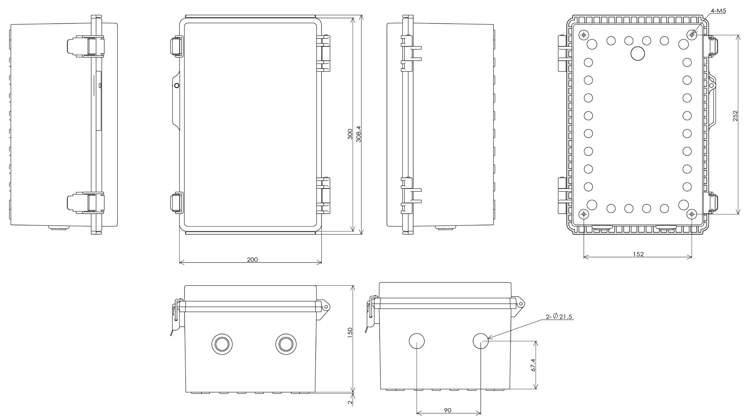
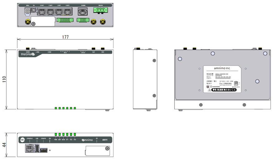
three-sided view
A three-view diagram is shown below.
AI Edge Gateway (outdoor version) #
This section describes the basic configuration of the AI Edge Gateway (outdoor version) main unit.
Front (lid open)
The configuration of the front view when the lid is open (with the lid of the SD card section opened) is shown below.
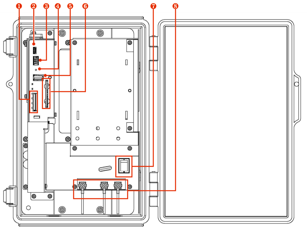
| No. | name | Description. |
| ❶ | SD card slot | SDXC type, UHS-I compatible. |
| ❷ | CONSOLE Port | Used to configure the Edge Gateway with a serial console, connected via a USB Type-C connector. |
| ❸ | DIP switches for configuration | Sets the startup mode of the edge gateway. |
| ❹ | PUSH switch | Used to shut down the Edge Gateway or restore it to factory settings. |
| (in Japanese) ❺ | USB port | Operates as a USB 2.0 host. |
| (in Japanese) ❻ | SIM card slot 0, SIM card slot 1 | Two SIM cards can be inserted in the SIM card slot. The priority level changes depending on the setting. By default, SIM 0 is used. |
| ❼ | power switch | Turns power on and off. |
| (in Japanese) ❽ | AC power input terminal | From left to right: FG, L (ungrounded side), N (grounded side). Screw shape is M4. |
Diagonal front view (lid open)
The diagonal frontal configuration is shown below.
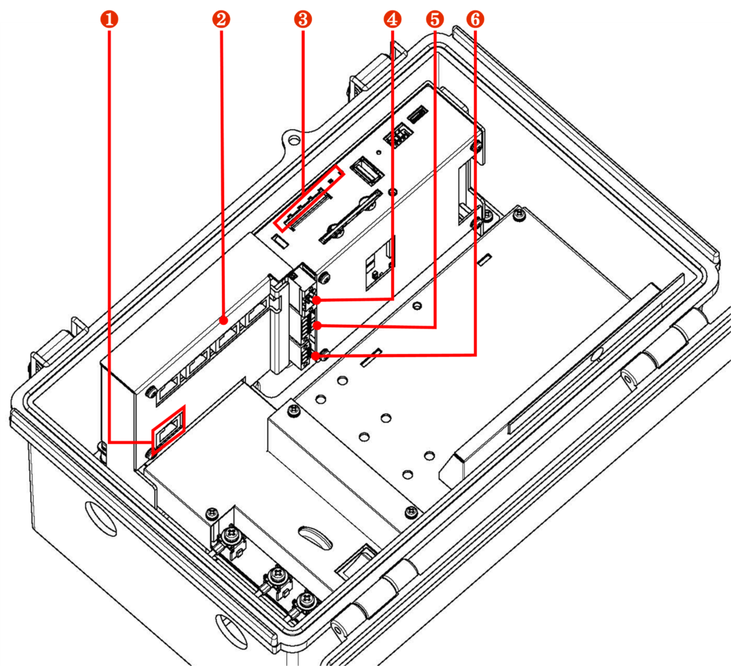
| No. | name | Description. |
| ❶ | ETH0 port | Standard Ethernet port with Gigabit Ethernet support. |
| ❷ | LAN0, LAN1, LAN2, LAN3 ports (4-port switch) | Standard Ethernet port with Gigabit Ethernet support, PoE (IEEE802.3at) compliant and PoE power supply. |
| ❸ | LED Indicator | PWR: Displays the power supply status. ANT: Displays the antenna status. MOB: Shows the line connection status of the communication module. ST1, ST2, and ST3: Specific states are displayed in combination with other indicators. |
| ❹ | RS485 port | Non-isolated type serial communication pins for connection to external devices. |
| (in Japanese) ❺ | D IN | Isolated type digital input terminal for connection to external devices. |
| (in Japanese) ❻ | D OUT | Isolated type digital output terminal for connection to external devices. |
three-sided view
A three-view diagram is shown below.