
This section provides a detailed description of each of the interfaces provided in the sensor connection gateway.
LED #
LED Indicator #
This section describes the lighting and blinking patterns of the LED indicators.
LED Icon Description
| LED | Description. |
| Indicates that the red and green LEDs are off. | |
| Indicates that the red and green LEDs are lit. | |
| Indicates that the red LED is on. | |
| Indicates that the red LED is blinking. (Blinking cycle is at 500ms intervals.) | |
| Indicates that the red LED is blinking. (Blinking cycles are at 125ms intervals.) | |
| Indicates that the green LED is on. | |
| Indicates that the green LED is blinking. (Blinking cycle is at 500ms intervals.) | |
| Indicates that the green LED is blinking. (Blinking cycles are at 125ms intervals.) |
Blank columns indicate that the LEDs are not controlled. Any change in state between items has no effect.
LED Status List
| (data) item | PWR | ANT | MOB | ST | remarks | |
| power disconnection (e.g. interrupted power supply) | | |||||
| power-on | ||||||
| during startup (of a machine, e.g.) | ANT, MOB, and ST turn on repeatedly in this order 500ms intervals | |||||
| Startup error occurred | ||||||
| Power outage | 125ms interval | |||||
| power disconnected (state) | ||||||
| shutdown process in progress | 500ms interval | |||||
| Antenna Level | ||||||
| unused | ||||||
| usually | RSSI (-73 dBm or higher) | |||||
| average (e.g. quality) | 500ms interval RSSI (-74dBm to -83dBm) | |||||
| during (a certain time when one did or is doing something) | 125ms interval RSSI (-84dBm to -93dBm) | |||||
| slightly weak | 125ms interval RSSI (-94dBm to -109dBm) | |||||
| weak | 500ms interval RSSI (-110dBm to -112dBm) | |||||
| outside range | RSSI (-113 dBm or less) | |||||
| state of connectivity | ||||||
| unconnected | ||||||
| More than a connection | ||||||
| 2G connection | 125ms interval | |||||
| 3G Connection | 500ms interval | |||||
| 4G connection | ||||||
| Firmware update in progress | ANT, MOB, ST blinking simultaneously 125ms interval | |||||
| Firmware update completed | ||||||
| Firmware update failure | ||||||
LAN port #
This section describes the lighting and blinking patterns of the LEDs on the LAN ports.
LED Icon Description
| LED | Description. |
| Indicates that the LED is off. | |
| Indicates that the green LED is on. | |
| Indicates that the green LED is blinking. | |
| Indicates that the orange LED is lit. |
LED Status List
| position | LED | Feature |
|---|---|---|
 | Link UP status | |
| Link UP and data transmission/reception status | ||
 | Link UP status at 1000BASE-T speed | |
| Link UP status at 100BASE-TX speed | ||
| Link UP (or No Link) condition at 10BASE-T speed |
DIP switch #
The DIP switch for configuration on the front of the sensor connection gateway sets the startup mode of the sensor connection gateway.
Explanation of DIP switch icons #
| DIP switch | Description. |
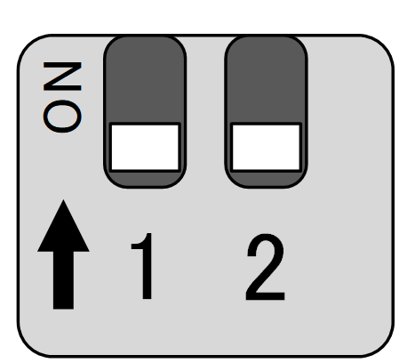
| ON state | |
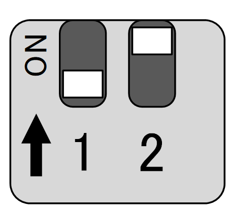
| OFF state |
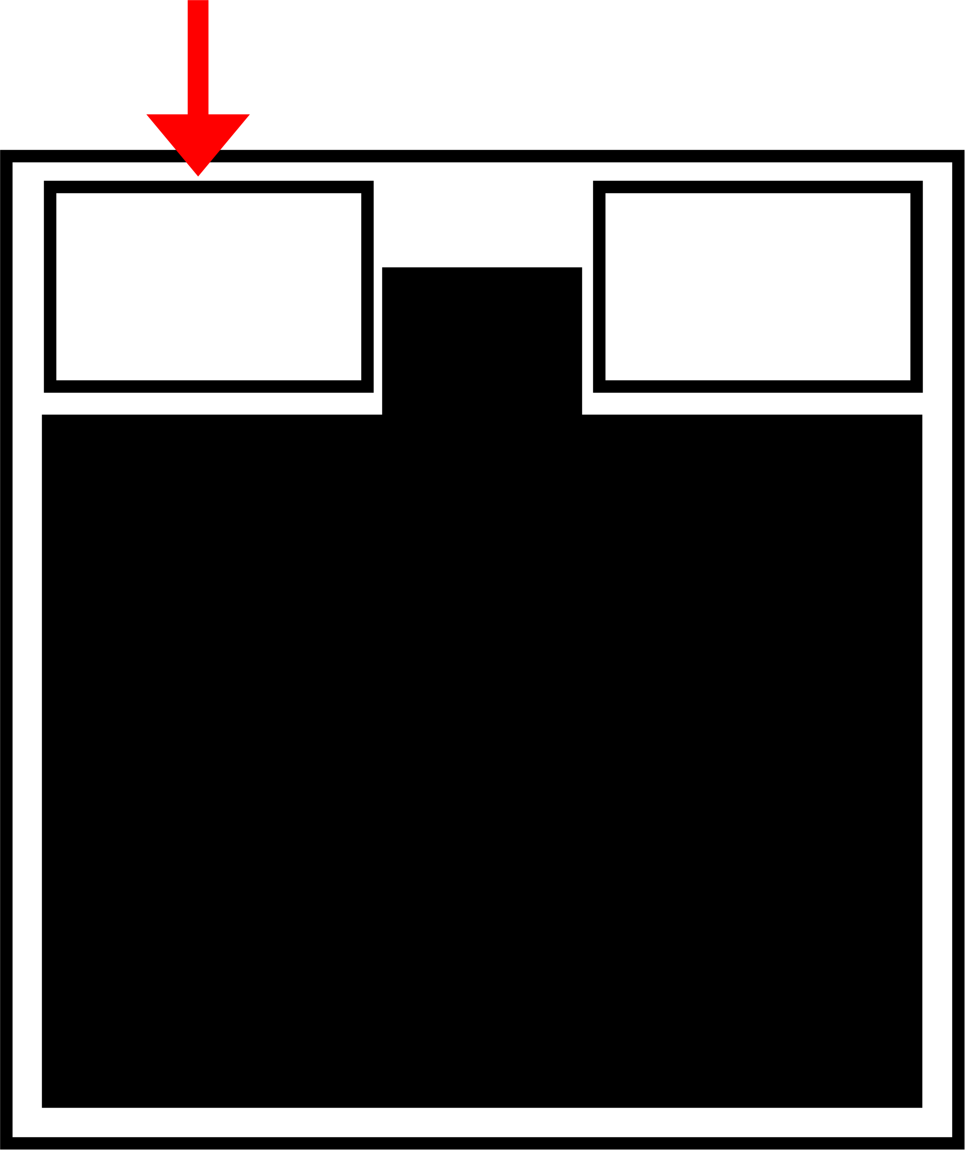
- Linux boot mode DIP switch settings
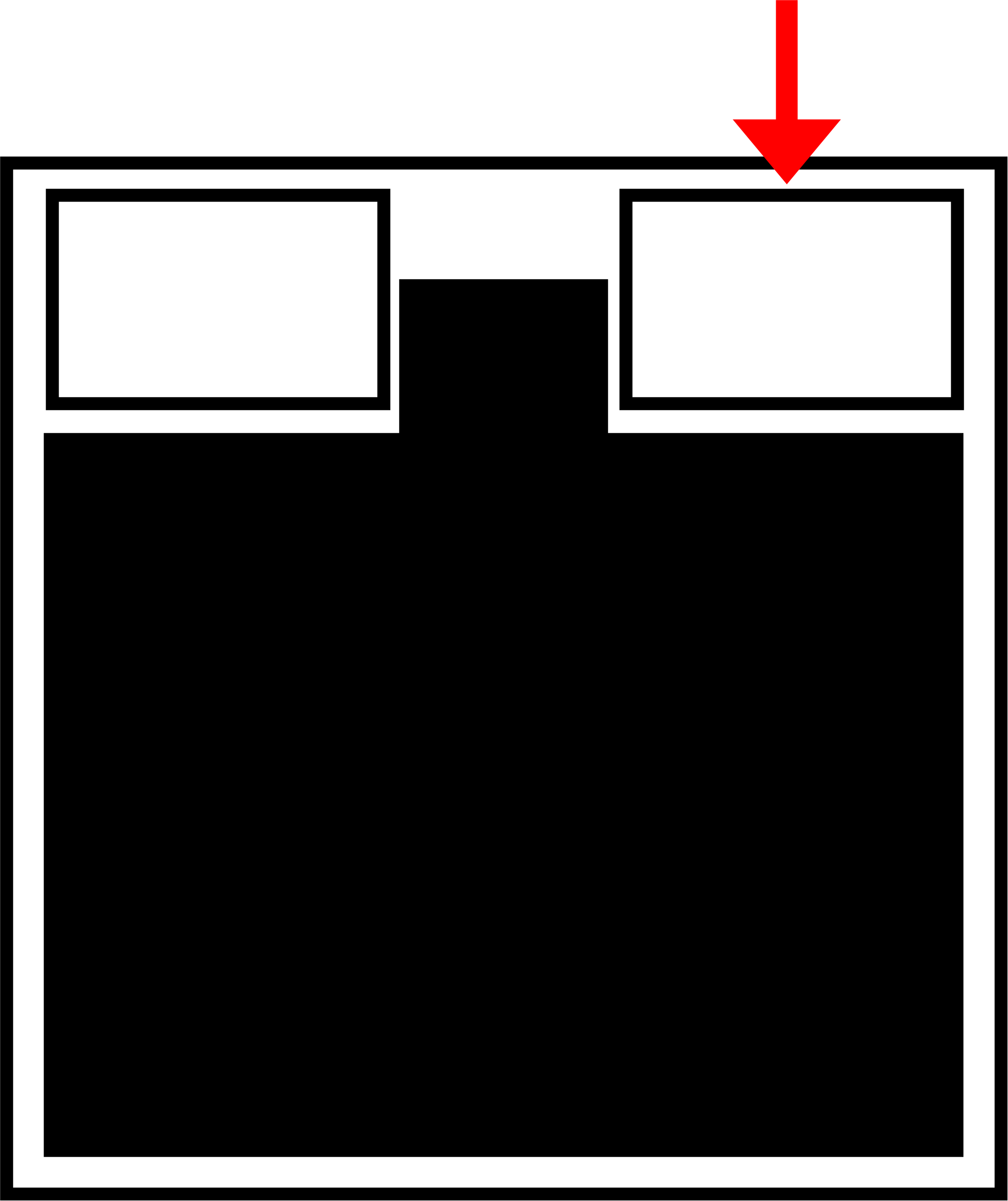
- DIP switch settings for U-Boot command mode
PUSH switch #
Holding down the PUSH switch for 3 seconds after booting the OS will put the sensor connection gateway into a power-off state.
If the power-off state continues for a certain period of time, the sensor-connected gateway is restarted by Watchdog Timer. This makes it possible to recover from a command operation (e.g., poweroff command) without having to go to the site, even if the command operation (e.g., poweroff command) was remotely powered off by mistake.
When the DIP switch is set to "U-Boot command mode," various settings are initialized to the factory defaults by turning on the sensor connection gateway with the PUSH switch pressed and holding the PUSH switch pressed for at least 3 seconds.
Note that setting files stored in the device will not be initialized. Therefore, if the device is rebooted after this operation is performed without writing to the settings file, it will start up with the settings before the settings are initialized.
CONSOLE Port #
Sensor Connection Gateway #
The Console of the sensor connection gateway is USB Type-C, so a USB Type-C cable can be used.
Depending on the destination PC, the FT230X Basic UART driver may need to be installed.
Please visit the following site to select the driver for your environment and follow the instructions to install it.https://ftdichip.com/drivers/d2xx-drivers/
Refer to the following table for CONSOLE port communication settings.
CONSOLE port communication settings (sensor connection gateway)
| (data) item | Contents |
| speed | 115200 bps |
| data | 8bit |
| parity | None |
| stop bit | 1 bit |
| flow control | None |
RS485 port #
In the sensor connection gateway, RS-485 is provided on a terminal block and the interface is not isolated. Half-duplex communication is possible. Termination resistors (120Ω) can be enabled or disabled. The maximum baud rate is up to 115.2 kbps.
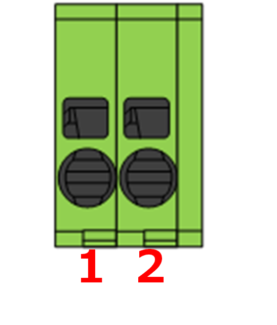
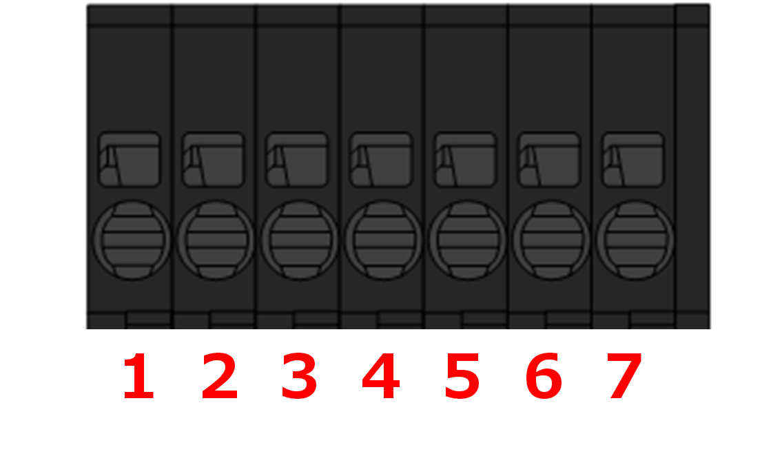
RS485 port pin number #
RS485 port pin assignment #
| pin number | pinout |
| 1 | Port 1 A(+) |
| 2 | Port 1 B(-) |
| 3 | GND |
| 4 | Port 2 A(+) |
| 5 | Port 2 B(-) |
| 6 | GND |
Serial communication specifications for RS485 port #
| (data) item | Contents |
| communication system | half-duplex communications |
| communication speed | 1,200 bps, 2,400 bps, 4,800 bps, 9,600 bps, 19,200 bps, 38,400 bps, 57,600 bps, 115,200 bps |
| data bit | 8bit |
| parity | Even parity, no parity |
| stop bit | 1bit, 2bit |
The connector part is PHOENIX CONTACT's PCB connector 1841500 SPTD 1,5/ 3-H-3,5 or equivalent.
D IN / D OUT port #
This section describes the digital input (D IN) and digital output (D OUT).
interface circuit #
The sensor connection gateway has a digital input (D IN) and a digital output (D OUT) interface. Each port can be used by connecting the appropriate wire to each pin.
D IN / D OUT Port Overview
| port | Description. |
| Digital input (D IN) | When the photo coupler of D IN is turned ON, a minimum current of 1.0mA is required. ● As a protection element, a 30V zener diode is mounted for isolation from the internal circuit. ● The photo coupler of D IN uses a bi-directional light emitting type LED. |
| Digital output (D OUT) | ● Uses a photomos relay ● Maximum current drive capability is 100mA ● Maximum on-resistance is 2Ω ● As a protection element, a 30V zener diode is mounted for isolation from the internal circuit Surge protection is required for items that generate a surge when turned on or off. |
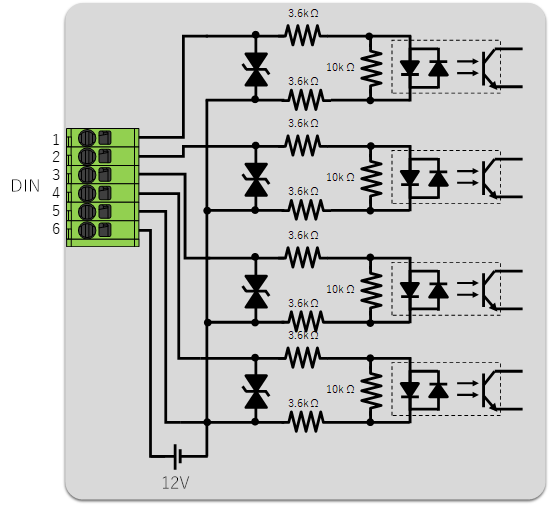
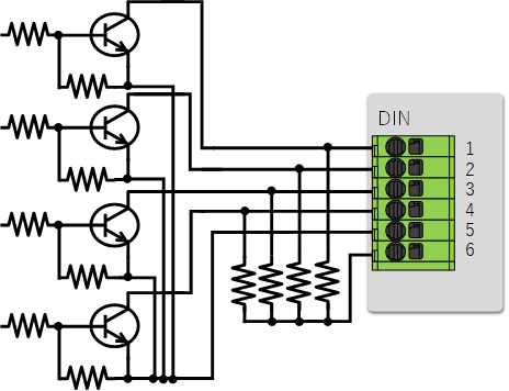
Below is a schematic of the internal interfaces associated with the digital inputs and outputs.
Digital input internal interface circuit diagram
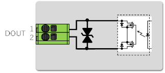
Digital output internal interface circuit diagram example
pinout
This section describes the pin assignments for the digital input (D IN) and digital output (D OUT) of the sensor connection gateway.
Digital input (D IN)
- It has four isolated digital inputs.
- When using an external power supply, the input voltage can be either 12V or 24V, and both positive and negative voltages are accepted.
- Internal impedance is approximately 7.2 kΩ.
- It has a common GND.
- When inputting pulses, a minimum pulse width of 500us can be input.
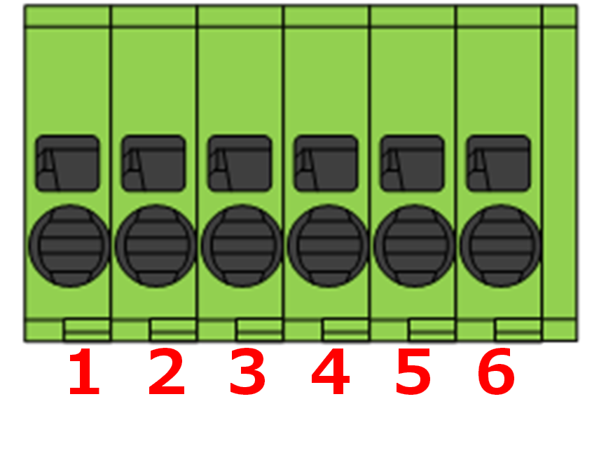
Connector part of digital input (D IN)
| Installation type | Model No. of connector part |
| Sensor connection gateway (AX30) | PHOENIX CONTACT PCB connector 1990779 SPT 1,5/ 6-H-3,5 |
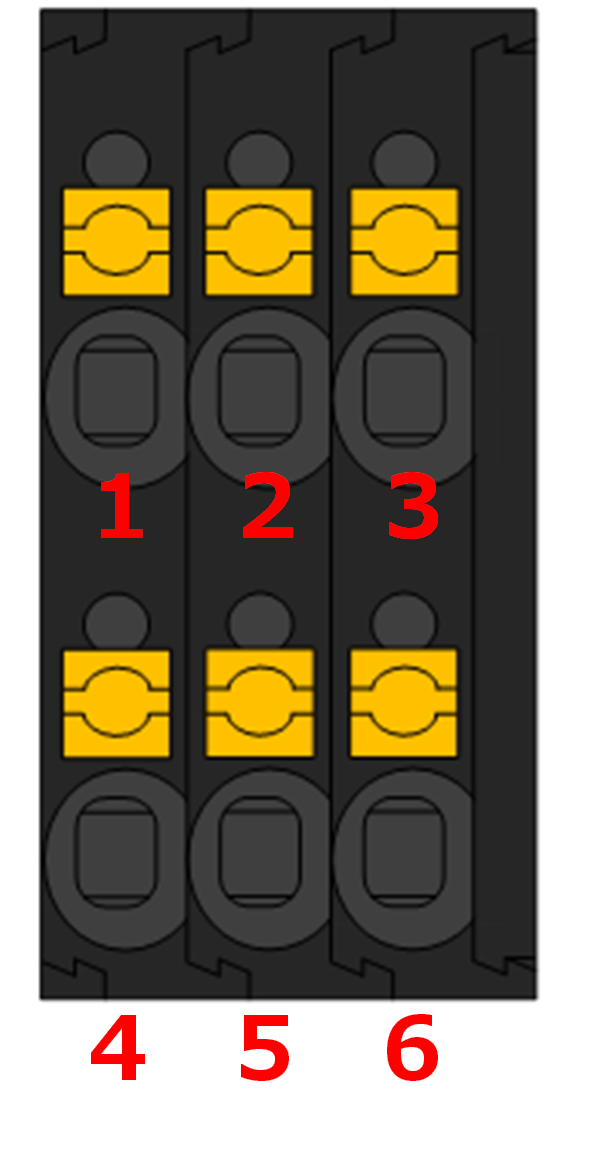
Digital input (D IN) pin assignment
| pin number | pinout | Contents |
| 1 | D IN0 | Digital input 0 |
| 2 | D IN1 | Digital input 1 |
| 3 | D IN2 | Digital input 2 |
| 4 | D IN3 | Digital input 3 |
| 5 | DIN Common | Digital input Common GND |
| 6 | DIN 12V | 13V±2V output for contact. 10mA max. |
Digital output (D OUT)
- Has one isolated digital output.
- A maximum current of 100 mA can be supplied by the photo-MOS relay output. However, no power supply is provided at the sensor connection gateway side.
Connector part of digital output (D OUT)
| Installation type | Model No. of connector part |
| Sensor connection gateway (AX30) | PHOENIX CONTACT PCB connector 1990737 SPT 1,5/ 6-H-3,5 |
Digital output (D OUT) pin assignment
| pin number | pinout | Contents |
| 1 | D OUT1 | Digital output 0 (no-voltage A contact) |
| 2 | DOUT Common | Digital output Common GND |
Connection example
An example of sensor connection gateway digital input (D IN) and digital output (D OUT) connection is shown below.
Digital input connection example
Digital transistor connection example
No-voltage contact switch connection example
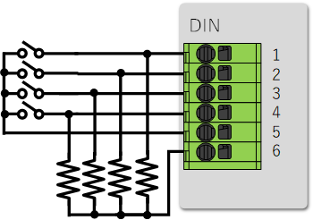
For the pull-up resistor to pin 6, select a value such that the current for each digital input is at least 1.0 mA and the maximum current for all ports is about 10 mA. (Example: When using 4 ports: 4.7kΩ x 4)
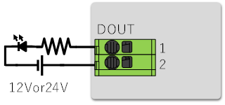
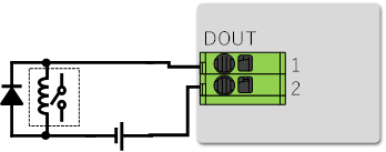
Digital output connection example
LED connection example
Relay connection example
A IN port #
This section describes the analog input (A IN).
interface circuit #
The sensor connection gateway has an analog input (A IN) interface. This port can be used by connecting the appropriate wire to each pin.
The specifications of each channel are different between AX30-A70JP-10 and AX30-B70JP-10.
A IN Port Overview
AX30-A70JP-10
| port | Description. |
| Analog input (A IN) | Up to 2 analog sensors with 4-20 mA output can be connected. ●Isolated from digital circuit section (but not between channels) |
AX30-B70JP-10
| port | Description. |
| Analog input (A IN) | Direct connection of one each of a pyranometer and thermometer (PT100) ●Pyranometer input can be from 0-20mV ●Thermometer (PT100) can measure from -20 to 100°C with three-wire input ●Isolated from digital circuit section (but not insulated between pyranometer and thermometer) |
pinout
This section describes the pin assignment of the analog input (A IN) of the sensor connection gateway.
Analog input (A IN)
Connector part of analog input (A IN)
| Installation type | Model No. of connector part |
| Sensor connection gateway (AX30) | DINKLE PCB connector 0177-3107 |
Analog input (A IN) pin assignment
| pin number | pinout | Contents |
| 1 | AIN 0+ | AX30-A70JP-10: 4-20mA sensor input 0+ AX30-B70JP-10: Solar radiation meter input + |
| 2 | AIN 0- | AX30-A70JP-10: 4-20mA sensor input 0- AX30-B70JP-10: Solar radiation meter input- |
| 3 | AIN 1+. | AX30-A70JP-10: 4-20mA sensor input 1 + AX30-B70JP-10: Thermometer input A |
| 4 | AIN 1- | AX30-A70JP-10: 4-20mA sensor input 1- AX30-B70JP-10: Thermometer input B |
| 5 | AIN 1b | AX30-A70JP-10: not used AX30-B70JP-10: thermometer input b |
| 6 | FG | Frame GND |
| 7 | FG | Frame GND |
AIN input specifications
4-20mA sensor input specification (AX30-A70JP-10)
| Input range | 0-24 mA |
| Maximum resolution | 16 bit |
| Conversion Cycle | Approx. 7.8 msec |
| Reference accuracy | ±0.1 % (at 23°C±2°C) |
| Temperature coefficient | ±0.02 %fs/°C |
| Input impedance | Approx. 250 Ω + Diode |
| Dielectric strength | 1500 V (non-isolated between channels) |
Solar radiation meter sensor input specifications (AX30-B70JP-10)
| Input range | 0-20 mV (sensitivity constant at 10 uV/W/m2 conversion, up to 2000 W/m2 of solar radiation) |
| Min. resolution | Approx. 1.6 W/m2 |
| Temperature Characteristics | Less than ±0.2 % (-20 to 50°C) |
| Response Time | 1 sec |
| non-linearity | Less than ±0.1 |
| Dielectric strength | 1500 V (not isolated from thermometer) |
Thermometer (PT100) sensor input specification (AX30-B70JP-10)
| access method | three-line input |
| Measuring range | -20 to 100 °C |
| resolution | 0.1°C |
| accuracy | ±0.3 °C |
| Temperature coefficient | ±0.02 %fs/°C |
| Response Time | 1 sec |
| Dielectric strength | 1500 V (not isolated from pyranometer) |
| Sensor current | Approx. 1 mA |
Various conversion formulas from AIN readings
This section describes how to convert readings at the analog input (A IN) of the sensor connection gateway to values for various uses.
4-20mA sensor input specification (AX30-A70JP-10)
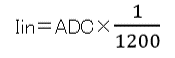
Iin: Input current value (mA)
ADC: Readings
Solar radiation meter sensor input specifications (AX30-B70JP-10)
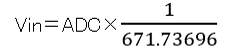
Vin: Input voltage value (mV)
ADC: Readings

P: Solar radiation ( kW/m2 )
S: Sensitivity constant of your pyranometer ( mV/kW/m2 )
Thermometer (PT100) sensor input specification (AX30-B70JP-10)
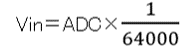
Vin: Input voltage value (V)
ADC: Readings
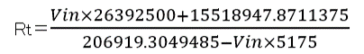
Rt: Resistance (Ω) of thermometer (PT100)
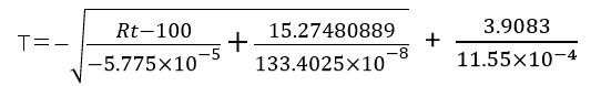
T: Temperature (°C)